How to 3D Print Replacement Parts That Fit on the First Try
Measure with calipers, pick the right clearance for press, snug or slip fits, and test before you print. A step-by-step guide to replacement parts that fit.
Key takeaways
- Measure the mating socket, shaft, or bracket with calipers instead of the broken part, since the original has warped or worn.
- Build clearance into the model by fit type: 0.0-0.1 mm for press fits, 0.15-0.25 mm for snug fits, and 0.3-0.5 mm for slip fits.
- Print a 20-minute tolerance test at several clearances before committing to a full-strength part.
- Split a model only when bed size, overhangs, layer-line strength, or hole orientation demands it, and cut along a flat face away from load points.
- Prefer 3MF over STL when your slicer supports it, because 3MF carries units, colors, and multiple bodies in one file.
To 3d print replacement parts that fit on the first or second try, run one pipeline: measure the broken part with calipers, model it with the right clearance for its fit type (slip, snug, or press), split it only if the geometry or overhangs demand it, then export an STL your slicer can print flat. Each stage below gets a concrete rule and a cheat sheet, so you spend an evening fixing the part instead of weeks learning desktop CAD.
How do you 3d print replacement parts that fit on the first try?
A replacement part that fits is the output of five stages, done in order: measure the broken part with calipers, model it, set the tolerance for its fit type, split it if printability demands it, and export an STL your slicer can use. Skipping a stage is what causes failed fits. Model without measuring and you're guessing. Guess the tolerance and a snug fit welds shut or a slip fit rattles. Ignore overhangs and you print a part that needs supports it can't afford.
The five stages at a glance
- Measure with calipers, not a ruler.
- Model the shape with the simplest workflow you can. Tools like Autodesk Fusion export meshes for printing, but the learning curve is real.
- Tolerance for the fit: snug, slip, or press.
- Split the part where a single print would fail.
- Export an STL or 3MF and check the mesh.
ShapeNook runs the same pipeline in your browser, and create-with-ai speeds up the modeling stage when the shape is simple.
How do you measure a broken part so the replacement actually fits?
Measure the socket, not the broken piece
The broken part is the least reliable reference in your hand. It warped when it failed, it's worn down, and it may be missing chunks. The hole it fits into, the shaft it spins on, or the bracket it clips to hasn't moved. Measure those mating surfaces and design to them.
The five measurements every replacement part needs
For most functional prints, five caliper measurements cover it:
- Shaft or hole diameter of the mating part (measure both directions of an oval, use the smaller).
- Center-to-center distance between any two holes or pins.
- Wall thickness of the socket or clip the part slides into.
- Depth of the pocket or the length of the shaft engagement.
- Overall envelope: height, width, length, so it clears everything around it.
Our templates at shapenook.com/templates include resizable boxes, lids and hooks, so for those shapes you type in your numbers instead of starting from scratch.
What to do when the part is too broken to measure
Reconstruct from the mating side. If the broken lug sheared off a bracket, measure the bracket's hole and design the lug from that. If a gear tooth snapped, count the teeth, measure the outer diameter, and measure a surviving tooth's width. When even that's gone, model the fit surface first, print a thin test sliver, and check it against the real socket before committing to the full part.
How much tolerance should you leave for a snug fit versus a slip fit?
Tolerance is the clearance you build into the model so two printed parts (or a print and an existing part) actually fit. A good starting point for FDM: engineering fit conventions give you the vocabulary, and hobbyist practice boils down to the ranges below, measured on the small dimension of your part.
Tolerance cheat sheet by fit type
| Fit type | Clearance per mating surface | Typical use |
|---|---|---|
| Press fit | 0.0–0.1 mm | Bearings, dowel pins, parts meant to stay put |
| Snug fit | 0.15–0.25 mm | Lids, clips, brackets you assemble once |
| Slip fit | 0.3–0.5 mm | Sliding drawers, hinge pins, anything that moves |
Round up for large flat contact areas: a 60 mm lid needs the top of the range, a 10 mm pin the bottom.
How your printer and material shift the numbers
Calibrated FDM printers (Bambu, Ender-class with a tuned first layer) sit near the low end of each range. If your prints run slightly oversized or you use a material that warps, add 0.1–0.2 mm. PETG and ABS shrink or ooze more than PLA, so lean toward the higher clearance. If you plan to sand, prime or paint the part, leave extra clearance, since coating thickness eats into it.
Print a tolerance test before the real part
Before printing a full-strength bracket, print a 20-minute fit test: the same joint at 0.1, 0.2, 0.3, and 0.4 mm clearances. Mark the one that fits with your calipers and use that number for the real part. It is faster than reprinting a two-hour part that is 0.1 mm too tight.
What's the simplest 3d modeling workflow for beginners making their first replacement part?
Start from a measured primitive, not a blank canvas
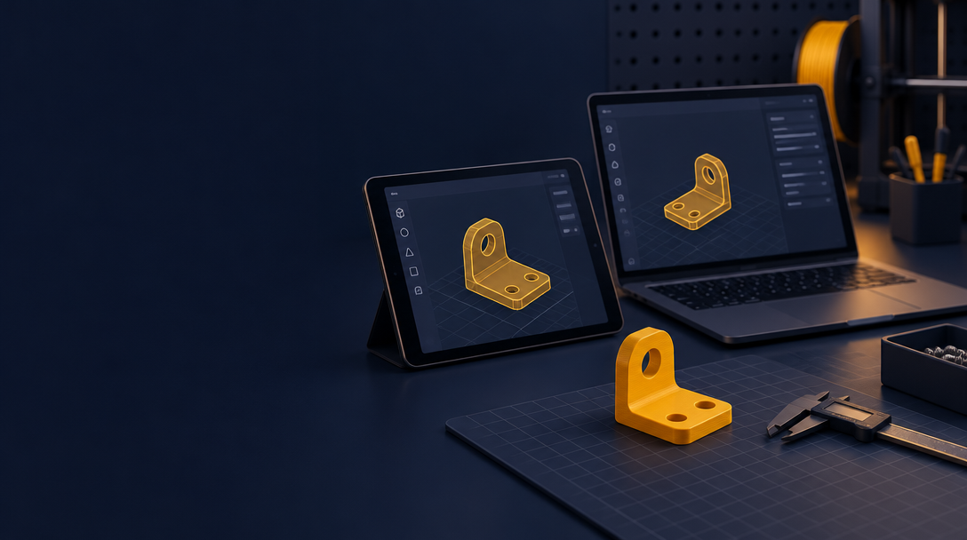
The fastest path from calipers to a printable part is four steps: build the broken piece from simple shapes at your measured dimensions, cut the holes, then add clearance to every surface that touches another part. That's it. A bracket is a box with holes; a knob is a cylinder with a cut flat and a D-shaped hole. Starting from a primitive that already matches the part's overall shape means every dimension you type comes straight off your calipers, so there's nothing abstract to learn before you're modeling something real.
This is why the workflow works without a CAD degree: you're never drawing from imagination, you're copying a physical object that's sitting on your desk. Block it out from boxes and cylinders sized to what you measured, then cut holes at the centers you marked. Add your tolerance to hole sizes and mating surfaces last, so it's one deliberate pass instead of guesswork baked into every dimension. If a hole is for a heat-set insert or a nut trap, model it at the insert's size plus clearance in the same pass. Four steps, one object, one export.
Browser and tablet options vs desktop CAD
TinkerCAD runs in a browser and is the usual beginner starting point. Fusion, Shapr3D, and Onshape are desktop-class tools with far more depth than a first replacement part needs. ShapeNook runs in the browser and on iPad, and is built around the measure-model-print loop rather than general CAD.
Where ShapeNook fits in this workflow
ShapeNook shortens this workflow: place shapes at your caliper measurements, cut holes with hole shapes, and print one fit test so holes, nuts and magnet pockets match your printer, with the overhang check (Plus) catching anything that would print in midair before you slice. When the part is done, export an STL or 3MF for your slicer; color and appearance settings carry over per our guide to export colors.
When should you split a 3d model into multiple printed pieces?
Four reasons to split a model
Split when the part is bigger than your bed, when it would need supports for large overhangs, when strength runs along a direction layer lines can't handle, or when one section needs a different orientation for clean holes. A single print that warps or snaps teaches you more slowly than two small test pieces.
Where to put the joint (and where not to)
Cut along a flat face, never through a hole, a nut trap, or a spot for heat-set inserts. Keep the joint away from the bend or load point: a bracket glued at its stress point fails at the glue line, not the plastic. If the broken original snapped in the middle, that's the worst place for your joint.
Joint options: dovetail, screw cap, glue flat
A glue flat is the default: two flat faces, CA glue or epoxy, done. A dovetail slides together and resists pulling apart, useful for parts you may disassemble. A screw cap works when you need to open the joint later, like a threaded lid on a handle. One caveat: STL files store no units or assembly metadata, so multi-part fits rely on your calipers and your tolerance math.
The 3MF format was created partly to carry that extra data between tools (3MF Consortium). In ShapeNook you can model both halves in one file, check the fit with a slip-fit tolerance, and export each piece as its own STL for the slicer. The same split-and-fit workflow works in TinkerCAD or Fusion; it just takes more manual measuring.
How do you export an STL file for 3d printing?
How to export an STL file from Fusion 360
Right-click the body (not the component) in the browser tree and choose "Save as Mesh." Pick STL or 3MF, set the refinement to "Custom," and push deviation and normal tolerance down to 0.01 mm for a small replacement part. The default "Medium" refinement can round off corners you measured with calipers. Export the body only, not the whole design, or you will bake setup geometry into your mesh.
Exporting from browser and tablet design tools
Browser and tablet tools export straight from the File or Share menu, usually as STL or 3MF with a quality dropdown. In ShapeNook, you model at exact dimensions, run the overhang check (Plus), then export the finished mesh to your slicer. The same rule applies everywhere: check the exported size in your slicer before printing. If the part reads 25.2 mm instead of 25 mm, your export units were wrong, not your model.
STL or 3MF: which to hand your slicer
STL is the safe default every slicer accepts, but it stores only triangles, so units and scale can get mangled in transit. 3MF carries units, colors, and multiple bodies in one file, and Bambu Studio and PrusaSlicer both prefer it. Use 3MF when your slicer supports it; fall back to STL for older setups. Either way, one body per file keeps troubleshooting simple.
Can you design a replacement part on an iPad without desktop CAD?
Yes, for most home-repair parts. ShapeNook runs in your browser or on an iPad (iOS app), with exact dimensions, print checks for overhangs, and export straight to STL or 3MF for your slicer. You can measure with calipers at the workbench, model the part with the right clearance for a snug or slip fit, and send it to the printer without touching a desktop.
What works well on a tablet
Parametric edits by typing numbers, simple splits for flat-bed printing, and quick fit-test revisions between prints. The touchscreen suits small functional print jobs better than a mouse does.
When you still want a desktop
Large assemblies, dozens of features in one part, or heavy filleting go faster with a full keyboard and screen. For a bracket, knob, or nut trap, the tablet covers it.
How do you verify fit before committing to a full-strength print?
Print a fit-check slice first
Before printing the real part, print a 2–3 layer thick slice of just the mating surfaces: the hole, the tab, or the slot that has to fit. It prints in minutes and uses a few grams of filament. Test it against the mating part with your calipers in hand, and mark the measured difference directly on the print.
If the fit is too tight, add half your slicer's line width (0.2mm on a 0.4mm nozzle) to that dimension and print the slice again. If it's loose, subtract the same amount. Two test slices usually get you within one line width of right, which is all a functional print needs.
Orientation, perimeters, and strength for the real part
Once the fit-check passes, orient the real part so layer lines don't cross the stress path. A bracket that bends along its length should print flat, not upright, because layer adhesion is the weak link. Put the fitted surfaces against the bed where possible so they print smooth.
For strength, add perimeters before infill: 4 walls on a functional part beats 40% infill for stiffness in almost every case. Then send the final STL or 3MF to your slicer and print the real thing, knowing the fit was already proven.
FAQ
What tolerance should I use for a lid that needs to spin on?
A spinning lid is a slip fit, so start at 0.3-0.5 mm of clearance on the mating diameter. Use the top of that range for wider contact areas, since a large flat surface drags more than a narrow pin. If your prints run oversized or you're using PETG, lean higher. A quick fit-test slice confirms the number before you print the full lid.
Can I 3d print a replacement part if I only have a photo of the original?
Not reliably for anything that has to fit. A photo gives you proportions, not dimensions, and perspective distortion makes measurements guesswork. Instead, reconstruct from the mating side: measure the socket, shaft, or bracket the part connects to, and design to those numbers. Use the photo only as a shape reference for the outline, then verify with a thin test print against the real socket.
Why does my replacement part fit in CAD but not on the printer?
Your model is exact, but your print isn't. FDM printers deposit slightly oversized lines, especially on small holes, which shrink effective dimensions further. If you modeled mating surfaces with zero clearance, the parts weld together. Add clearance for the fit type, print a tolerance test at several clearances, and check whether your slicer or export step scaled the part unexpectedly.
Is STL or 3MF better for replacement parts with multiple pieces?
3MF, when your slicer supports it. STL stores only triangles, so units, scale, and assembly intent can get mangled between tools, which matters when two printed halves have to meet at a joint. 3MF carries units, colors, and multiple bodies in one file, and modern slicers like Bambu Studio and PrusaSlicer prefer it. Fall back to STL only for older setups.